In a recent BERMAD webinar, “How to Design & Implement a Pressure Reducing Station for Extreme Pressure Difference,” Micha Baer, our Waterworks Application Engineer, talked about the challenges in dealing with extreme high pressure in a water supply pipeline.
<<Missed the webinar? Watch Now>>
During the webinar, questions regarding pressure relief valves, sizing valves and cavitation damage were addressed:
Q: What type of pressure relief valves did you use at each stage and how did you select the size?
A: Pressure relief valves were selected according to the pressure rating and required pressure setting:
-
Before the first stage: PN100 Nitrogen Charged Relief Valves were selected; relief setting is 85 bars
-
After the first stage: BERMAD's PN40 800 valves were selected; relief setting is 38 bars
-
After the second stage: BERMAD's PN25 700 valves were selected; relief setting is 20 bars
-
After the third stage: BERMAD's PN16 700 valves were selected; relief setting is 12 bars
Each valve was selected using BERMAD’s sizing program.
<<Missed the webinar? Watch Now>>
Q: Is it necessary to install a relief valve before the first stage as well in the case of valve suddenly closing?
A: The extreme high pressure in this Pressure Reducing System required proper safety measures, including Pressure Relief Valves after each one of the three reduction stages. The Pressure Relief Valve before the first stage protects the lower parts of the supply pipeline from surges in case the flow is reduced too quickly. This is an extra layer of safety over the controlled and staggered closing of the flow in the system.
Q: Why did you choose the Nitrogen Charged Pressure Relief valve?
A: The Nitrogen Charged PN100 Pressure Relief valves were chosen over mechanical (spring) types after considering the pros and cons of both options. BERMAD’s accurate, compact, quick responding Nitrogen Charged Pressure Relief Valves are readily available.
<<Missed the webinar? Watch Now>>
Q: How do pressure relief valves protect the system from surges? Why not use surge tanks?
A: The selected Pressure Relief Valves are actually Quick Pressure Relief Valves, with a configuration that allows for a very quick response (split seconds) and quick opening, as well as controlled slower closing to avoid secondary pressure surges.
Surge tanks for this system would have to be PN100 to suit the high pressure and extremely large in order to handle the large volume supply line. The high manufacturing costs of such tanks together with the limited site area, make this an impractical option.
Q: What are the basic guidelines for valve size selection?
A:When sizing a control valve, many parameters need to be considered including upstream pressure, downstream pressure, flow and the application it is used for.
BERMAD Sizing is a sophisticated program which is based on sizing standards, laboratory tests and vast experience. It simultaneously relates to three sets of actual working conditions, such as minimal, normal and maximal flow. The displayed results allow the user to conveniently and accurately check various valve types, sizes and configurations, and to select the most suitable solution. BERMAD’s engineers will be happy to help with sizing the valves. Register for BERMAD’s Sizing Program here.
Q: What Cavitation Index did you consider during the design & what measures did you take to avoid cavitation damage?
A: Dividing the load over three pressure reduction stages helped to reduce the cavitation load on each of the valves to a level where no other measures were required for cavitation protection. We used the BERMAD Sizing program to check and verify that none of the valves would be impacted by cavitation damage.
The Cavitation Index relates to the formula – σ=(P2a-PVa)/(P1a-P2a).
The accepted industry guidelines are: >1 = No cavitation; 0.5-1 = Mild cavitation; 0-0.5 = Severe cavitation
BERMAD has various solutions for reducing cavitation load other than multiple stage reduction including Double Cavitation Cage, cavitation resilient materials, and more.
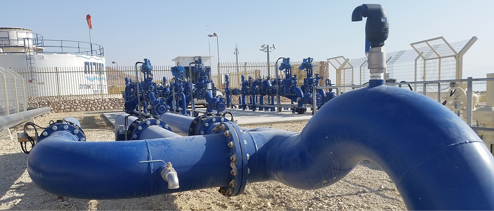
How to Design & Implement a Pressure Reducing Station for Extreme Pressure Difference Webinar
Developing a complete water supply solution for the lowest place on earth presented numerous challenges. 60 kilometers of pipeline connect the Dead Sea resort and farming areas (380 meters below sea level) with the Tzafit reservoir facility (450 meters above sea level). The difference in height creates massive pressure in the pipeline, rising to 83 bar. Register to watch the recording of the webinar.