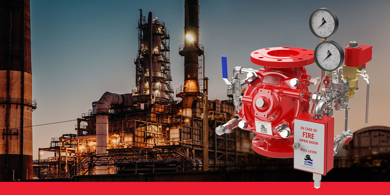
In municipal fire pump applications, a water booster pump system is often used to take water from a public service main or private use water system. The booster pump serves the purpose of increasing the existing water pressure to one suitable for the fire protection system. When designing or installing such a water booster pump, it is important to consider certain critical issues specific to water booster pumps.
Maintaining sufficient residual pressure at the inlet
If the water is taken from a municipal main pipe, Net Positive Suction Head Required (NPSHR) must be considered. This means that at "worst case conditions" (often considered as 150% of the rated pump capacity), there must be sufficient residual pressure at the inlet of the pump for the continued function of the municipal supply. This is especially critical for fire protection because the municipal piping might go on to supply other fire protection systems, even in the same building. As outlined by the NFPA 20 standard, "It should be noted that the use of residual pressures of less than 20 psig (1.4 barg) are not permitted by many state health departments."
Where the Authority Having Jurisdiction or AHJ has no specific requirements regarding the NPSHR, there still remains a primary concern as to the ability to maintain sufficient residual pressure to prevent the development of negative pressure at any point in the street mains. Negative pressures could result in the collapse of the mains or other water system components, or back-siphonage of polluted water from some other interconnected source.
Avoiding cavitation in low pressure scenarios
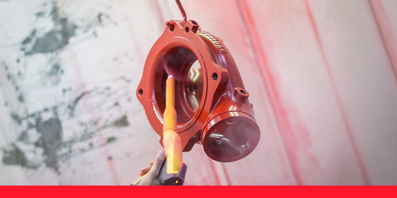
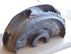
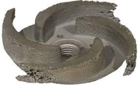
Another problem emerging from a low suction pressure is the possibility of cavitation damage to the pump. Cavitation is a phenomenon that occurs when the water pressure falls to vacuum state and as a result, vapor bubbles are created. When the pressure is very low (or even negative) at the inlet suction of a pump, vapor bubbles form and pass into the pump. Under these conditions they do little damage. However, when the vapor bubbles reach the higher pressure created by the pump towards the outlet side of the impeller, they implode. This implosion of vapor bubbles creates very high pressure jets/waves that can rapidly weaken and erode the metallic parts of the pump, pit the metal and eventually drastically reduce pump functionality.
The following images depict pump impellers that have been damaged by cavitation resulting from insufficient suction pressure.
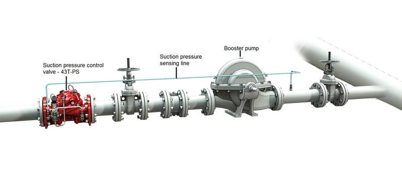
If the possibility of insufficient suction pressure does exist, then the most common and efficient solution is the installation of a pump suction control valve. This valve should be situated at the outlet side of the pump, with a sensing line to the suction or inlet side of the pump. When necessary, or when the suction pressure falls below the allowable or set minimum, the valve will regulate the inlet pressure to stay above a preset minimum.
Selecting valves for optimal booster pump operation
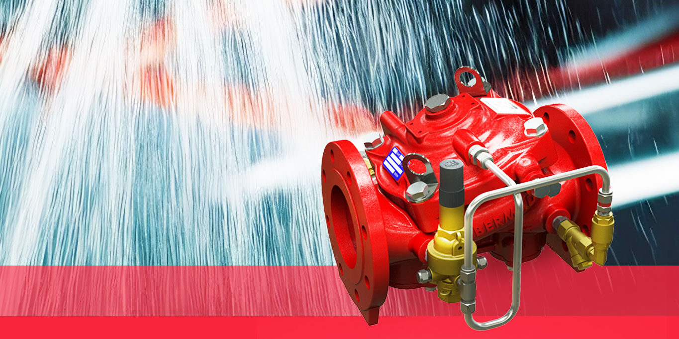
When choosing a valve for this function, one of the main considerations after reliability should be the flow efficiency of the valve. It is important to use a valve that does not unnecessarily hinder the flow, even when fully open. A valve with a clear, unobstructed flow path is highly preferable.
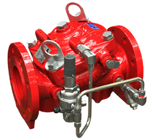
The BERMAD 43T-PS adjustable pump suction pressure control valve is a good example of a valve suited for this function. It features the high reliability inherent in elastomeric valves as this type of valve does not have bearings or shafts that might stick if the valve is dormant for long periods. When fully open and not modulating the suction pressure, the exceptionally low flow resistance and straight-through, unobstructed flow path of this valve allows the pump to continue to function efficiently, with minimal hindrance to delivering firewater to the extinguishing devices.
The BERMAD 43T-PS remains fully open whilst the pump suction head or pressure level at the pump inlet remains above the preset minimum (NPSHR). If the suction pressure falls below the preset minimum, the pilot valve senses this via the sensing line and causes the main valve to modulate, keeping the pressure above the set level.
Typical Installation of a booster pump suction valve
Questions about fire protection system design?
BERMAD provides technical support to fire protection system designers and engineers. For more information about fire protection system design, visit our fire protection knowledge center. Or, to speak with a BERMAD fire protection representative in your region, contact us here.