Water hammer due to valve closing is unfortunately a common risk as valve closing dramatically reduces flow – "blocking" the water path. In this short blog, we look at the problem and recommended solutions.
Problem:
Water hammer caused by valve slamming at closing.
- Valve: IR-2"-100 series, commanded by external pressure (no specific application is detailed)
- Working pressure: 50 meters / 73 psi
- Command pressure: Not specified
- Flow: 4 l/s (14.4 m3/h) / 63.4 gpm
- Flow velocity: 2m/s / 6.5 f/s
Possible Cause:
Based on available information, slamming is assumed to be caused by one or both of the following reasons:
- Command pressure is much higher than valve inlet pressure
- Pneumatic command
Solution:
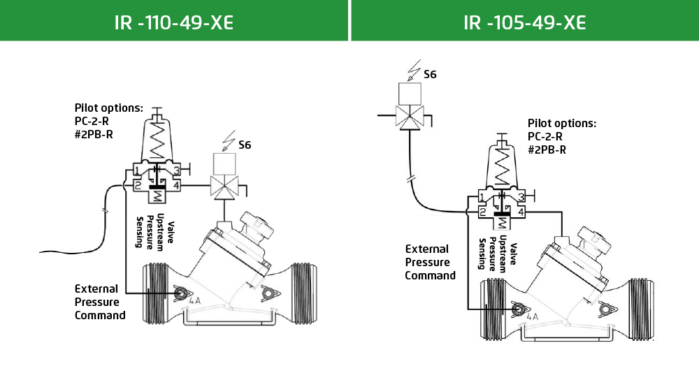
We propose adding feature #49 (upstream pressure rise prevention at closure) to existing control loop shown in the illustration below:
Pilot will restrict flow into control chamber as pressure upstream climbs towards set point (cutting it completely if it rises above set point).
Features & Benefits:
- Dynamic closing speed in responds to pressure rise (higher upstream pressure = bigger flow restriction through the pilot and slower closing speed)
- Closing maneuver freeze if upstream pressure rises above set point (pilot will momentarily cut command pressure flow until upstream pressure returns to permitted values)
- Closing maneuver resumes once upstream pressure drops below set point.
- Unrestrained closing speed during most of actuator's stroke – minimum effect on total closing maneuver duration (as long as upstream pressure remains within normal parameters, closing speed is unrestricted, unlike a solution based on a needle valve which restrains flow regardless of pressure fluctuations)
- Lower risk of loop clogging (for small control chamber displacement volume - a solution based on needle valve will offer very narrow flow through cross section that can clog by particles smaller than loop inlet filter. A pilot will only reduce passage upon pressure rise, opening the pass once pressure stabilizes, washing trapped particles out of the loop)
Setting Considerations:
- In 3 way loop with remote control - Pilot setting should be higher than maximum static upstream pressure (to allow valve opening) – if not additional elements should be added to control loop
- Pilot setting should be lower than nominal pressure of the installation (defined by the lowest pressure rating element installed upstream of the valve)
Control Loops:
This can be achieved using 3 different pilots – all equipped with remote sensing:
- PC-2-R: 2 way pressure reducing with remote sensing
- #2PB-R: 2 way pressure reducing pilot with remote sensing
- PC-S-R: 2/3 way servo pilot with remote sensing
The loops below show the solution using PC-2-R or #2PB-R, with local or remote control (command pressure is external in both cases).
Interested in learning how flow control valves maintain a constant pre-set maximum flow regardless of fluctuating demand or varying system pressure? Read the blog to learn more about the valves and flow control applications in irrigation systems.